3D-DOCTOR Frequently Asked Questions
3D-DOCTOR Basics
- What is 3D-DOCTOR?
- What are the differences between 3D-DOCTOR and other 3D modeling and visualization products?
- Can you show me how 3D-DOCTOR works?
- What's are the steps to create 3D rendering from 2D image slices?
- What display settings should I use to run 3D-DOCTOR?
- Can I use the demo version for my work?
- What platforms (Operating Systems) does 3D-DOCTOR run on?
- What are the licensing options? USB Dongle, Software key, etc.
- Does 3D-DOCTOR run on a Unix system?
- Does 3D-DOCTOR run on a Linux system?
- Does 3D-DOCTOR run on a Macintosh system?
- What's a reasonable set up for my PC to run 3D-DOCTOR?
- What's the ideal hardware set up to run 3D-DOCTOR?
Applications
- How do I calculate the volume of 3D object in a CT/MRI scan?
- What format should I use to export model to SolidWorks?
- What 3D format should I use to export model to 3DSMAX?
- Can I use 3D-DOCTOR to create models for finite element analysis (FEA)?
- Can I create 3D models for rapid prototyping/3D printing using 3D-DOCTOR?
3D Formats, File Handling, and Reslicing
- What image formats does 3D-DOCTOR support?
- What 3D formats does 3D-DOCTOR support for export?
- What types of images can be used in 3D-DOCTOR?
- Is there any limit on image size?
- How to convert DICOM images to TIFF or JPEG?
- How do I define slice thickness?
- How do I bring my images into 3D-DOCTOR? What can be done if the images are on film?
- Can I process color images using 3D-DOCTOR?
- How do I import the raw image files from the Visible Human Project?
- How do I put a stack of 2D image slices into a volume?
- Can I reslice my 3D image along another axis?
- How do I reslice a 3D CT/MRI image at an arbitrary angle?
- How to convert SLC format files into STL format in 3D-DOCTOR software?
- How to move 3D-DOCTOR project files to a new location?
- What is deconvolution?
- What is a point spread function (PSF)?
3D Image Segmentation & Editing Tools
- How do I define an ROI (region of interest) for segmentation?
- What does segmentation do?
- How do I split/cut objects for 3D rendering?
- Can I generate object boundaries manually?
- How do I use color image classification and segmentation?
3D Surface Modeling, Rendering & Animation
- What is 3D surface rendering?
- How do I create a 3D surface model from my images?
- How do I create a smoother model from a low resolution scan (wide spacing between slices)?
- How do I adjust the scale (X, Y, Z) of my 3D rendering?
- How do I create a 3D surface model using contour data from other programs?
- How do I split/cut objects for 3D rendering?
- How do I combine and compare multiple 3D models?
- How do I display image slices together with 3D models?
- How do I control the animation of objects separately?
- How do I create a video of flying through an object?
3D Volume Rendering
Measurement, Report, Quantitative Analysis, and Presentation
- How do I get images created by 3D-DOCTOR into my presentation program, for example, PowerPoint?
- What types of measurements can be done by 3D-DOCTOR?
- Can I calculate the 3D volume of my 3D surface model?
- How do I calculate the surface area of a 3D surface model?
- How do I create object report for density measurement?
- How do I get object size analysis report?
- How do I calculate the histogram of 3D objects?
- How do I get 3D measurements on an object, for example, along the airway?
- How do I create a movie or animation using 3D-DOCTOR?
3D Image Registration, Fusion and Comparison
- Can I register two 3D images for fusion or comparison?
- How do I create an image mosaic using 3D-DOCTOR?
- How do I compare a pair of CT/MRI images using 3D-DOCTOR?
- How do I create a 24-bit RGB color image from a grayscale image?
- How do I combine image slices to create a fusion?
Image Slice Alignment & Reslicing
- Can I automatically align the slices in a 3D image?
- How do I manually align image slices?
- How do I reslice an image with uneven spacing between slices?
3DBasic Scripting Tool
- Is there a scripting tool in 3D-DOCTOR for customized programs?
- Can I run 3DBasic script outside of 3D-DOCTOR?
What is 3D-DOCTOR?
3D-DOCTOR is an advanced, 3D imaging software developed by Able Software LLC. It does 3D image segmentation, 3D surface modeling, rendering, volume rendering, 3D image processing, deconvolution, registration, automatic alignment, measurements, and many other functions.
Back to TopWhat are the differences between 3D-DOCTOR and other products?
3D-DOCTOR uses its unique vector-based technologies to create 3D models from volumetric images such as CT, MRI and microscopy images. The following lists some of the main features of 3D-DOCTOR and the differences between 3D-DOCTOR and other packages:
- 3D-DOCTOR has the US FDA 510K clearance for medical imaging and modeling applications.
- Unique vector-based technologies for faster 3D model creation and easy editing.
- Surface model has less triangles while maintaining all details for high quality rapid prototyping applications.
- Smart memory management with no limit for the number of slices to be used. It has been used to process images with over 2000 slices.
- Volume calculation, 3D measurement for quantitative analysis applications.
- Handles DICOM and other image formats, such as TIFF, JPEG, PNG, GIF, BMP, Interfile and RAW (vendor proprietary formats).
- Works with both grayscale and color images (color classification and separation)
- Supports CT, MRI, PET, microscopy, industrial CT, scanned film images, boundary slices, slice data and XYZ points.
- Advanced 3D Image Processing Functions: image registration for multi-modality application, image fusion, image resizing, image reslicing, image slice alignment, etc.
- Write your own programs with 3DBasic script to automated frequently used steps.
- 3D Output Formats: STL (ASCII and Binary), VRML, DXF, 3D Studio, IGES, Wavefront OBJ, PLY and more. Reasonably priced. All functions are tightly integrated in a single easy-to-use package. No need to buy any additional expensive modules.
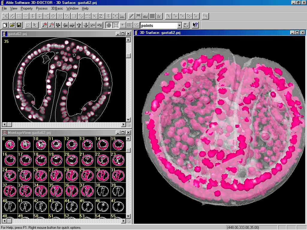
Can you show me how 3D-DOCTOR works?
We have created several video clips to show
you how 3D-DOCTOR works.
What's are the main steps to create 3D rendering from 2D image slices?
The following lists the main 3D-DOCTOR functions and steps you
can use to create 3D rendering from your 2D image slices:
1. File/New Stack to add the slices to the stack list and open it.
Or the File/Open command if the slices are already in a list or
a single image file.
2. Function Keys F2 and F3 to zoom in and out. F5 and F6 to
switch
to the previous and next image slice. Click on the animation tool bar to
fly through the slices. View/Image Contrast to adjust display contrast,
etc.
3. Edit/Calibrations to enter image spatial/spectral resolution.
4. Edit/Object Settings to add new object groups for holding
the boundary
data.
5. Use 3D Rendering/Auto Segment and define the number of
objects
to be segmented for fast automatic segmentation. You can also use the
3D Rendering/Interactive Segment or Edit/Boundary Editor to trace
object boundaries automatically or manually. The boundary data will be
used by the following steps.
6. Use the 3D Rendering/Surface Rendering commands to create
3D
surface models. When the 3D surface models are displayed, use
View/Object to change the transparency and color properties and
functions
under Tools submenu for further analysis.
7. Use the 3D Rendering/Volume Rendering to create 3D volume
rendering
for 3D visualization.
8. Use Edit/Object Report and Boundary Report to get
quantitative analysis of
your image.
What image formats does 3D-DOCTOR support?
3D-DOCTOR supports a variety of image formats in both 2D and 3D. These formats include DICOM, TIFF, JPEG, BMP, Interfile, GIF, PNG and RAW. Other non-standard image formats are also supported, but only with known dimensions (number of columns, rows and planes), bit depth per pixel, little endian or big endian, and the size of file header.
Back to TopWhat 3D formats does 3D-DOCTOR support for export?
3D surface models created using the surface rendering commands can be saved as AutoCAD DXF, IGES, STL (ASCII and Binary), 3D Studio 3DS, VRML, Wavefront OBJ, PLY, raw triangles, and 3D-DOCTOR's own binary format.
3D models created by 3D-DOCTOR are polygonal models, not NURB (non-uniform rational B-splines) models. The models are saved in the form of surface polygons and triangles when exported to the above formats, including IGES. Many NURB based CAD software supports polygonal model and have functions to import them as surface body, solid body or graphics model. There are also software tools available to convert a polygonal model to a NURB model.
Object boundary contours can be saved as AutoCAD DXF, IBL (for Pro/Scan), ASCII boundary (BND), and XYZ formats.
Download sample files created by 3D-DOCTOR from the pelvis CT image in DXF, STL, VRML, OBJ, PLY, 3DS and IGES format to check the compatibility with other programs you use. The files are zipped for faster downloading. Click the right mouse button and use Save Target As to get the file:
- DXF Format (AutoCAD DXF)
- IGES Format
- VRML Format
- STL Format
- 3DS Format (3D Studio)
- OBJ Format (Wavefront OBJ)
- 3D-DCOTOR's 3D .SUF Format
- 3D volume rendering can be saved as VOL and XYZ formats.
What types of images can be used in 3D-DOCTOR?
3D-DOCTOR can process a wide variety of images, including CT (computed tomography), MRI (magnetic resonance imaging), microscopy, industrial CT, seismic wave data, scientific volume data, 3D contours, and 3D cloud points. Images can be obtained from medical imaging devices or scanned from films or other image sources. 3D-DOCTOR supports TWAIN-compatible imaging devices and functions for cropping medical film images.
3D-DOCTOR supports grayscale images in 4, 8, 12 and 16 bits, 1-bit black/white images, and 8 and 24 bit color images.
Back to TopIs there any limit on image size?
3D-DOCTOR can handle very large 3D volume images thanks to the efficient memory management implementation. 3D-DOCTOR does not load an entire 3D volume into memory for processing, instead it only keeps what's needed in memory to get the best performance. 3D-DOCTOR is designed to handle image sizes way above what today's scanners can produce.
It is always recommended to add more memory (RAM) to reduce disk swapping and improve performance. 512MB RAM should be a reasonable starting point for most 3D medical images.
Back to Top
How to convert DICOM image files to TIFF or JPEG?
Since most DICOM
images are 16-bit and most image viewers for TIFF or JPEG files can
only support 8-bit pixel, you'll need to convert DICOM images to 8-bit
first and then save them to TIFF or JPEG format. The following lists
the steps:
1. Use the "New Stack" command to put the DICOM image slices into a
stack. Open the image stack.
2. Use the "Image/Conversion/Convert to 8-bit Grayscale" to create a
new 8-bit image file with all image slices. Use a TIFF file as the out.
3. Open the converted 8-bit image. Use the "File/Save/Save Image As" to
save the stack to TIFF or JPEG files. Check the box "Separate Image
Slices to Separate Files".
How do I bring my images into 3D-DOCTOR? What can be done if the images are on film?
Images are brought into 3D-DOCTOR by file. You can read an image file directly from a server where the image is stored when direct network access is available. If direct access is not available, you can copy the image file to a removable storage media (ZIP disk, CD, or tape) and then move the data file to the system where 3D-DOCTOR is installed. Read the image file into 3D-DOCTOR and start from there.
If your image is on multiple films where each film has a matrix of slices, then simply scan the films using a regular image scanner with a transparency kit or a film scanner. Bring the scanned images into 3D-DOCTOR and then use the template based Crop Film command to separate the slices for 3D visualization with just a few simple mouse clicks.
Back to TopCan I process color images using 3D-DOCTOR?
Yes, 3D-DOCTOR supports both 24-bit and 8-bit color images. The 3D Rendering/Segment Object function lets you segment both color and grayscale images to get object boundaries. You can also use the Image/Processing/Color Classification function to group the colors and then extract boundaries using the segmentation function. Color images can also be used in 3D Volume Rendering.
You can convert color images to grayscale using the Image/Conversion function.
Back to Top
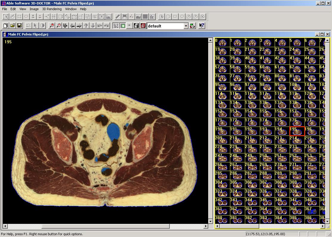
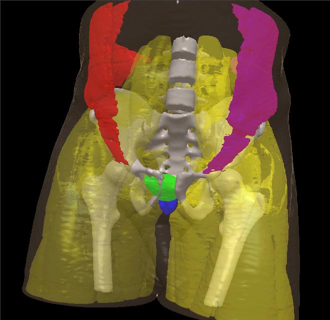
How do I import the raw image files from the Visible Human Project?
3D-DOCTOR can import the raw images files from the Visible Human Project for 3D rendering and modeling. Many 3D-DOCTOR users have successfully used the datasets to create anatomical model for research, education, product design, finite element analysis and other applications.
The Visible Human Project® is the creation of complete, anatomically detailed, three-dimensional representations of the normal male and female human bodies. Acquisition of transverse CT, MR and cross sectional images of representative male and female cadavers has been completed. The male was sectioned at one millimeter intervals, the female at one-third of a millimeter intervals.
To import the files, use the "File/Raw Image File Import/Multiple Files" command. Add the raw data files to the list and enter the image size information (described in the README.TXT file in the image file folder).
For example, if you are importing the color raw image files, the parameters will be entered like this:
Number of Columns: 2048
Number of Rows: 1216
Bits Per Pixel: 8
Number of Bytes to Skip: 0
Photometric Display: RGB Color
Little Endian: checked
For the Calibration: X, Y are 0.33mm, Z = 1 mm
Here is a screen shot of the color image imported into 3D-DOCTOR and models created (Image courtesy of H. Gall, CIRS):
What is 3D surface rendering?
3D-DOCTOR's, 3D surface rendering commands create 3D surface models from object boundary lines or contours. The 3D surface model consists of triangle faces. Multiple objects can be combined together using 3D surface rendering.
There are 2 surface rendering commands in 3D-DOCTOR: Simple Surface Rendering and Complex Surface Rendering. They both create 3D surface model but use different algorithms and are suitable for different objects.
The simple surface rendering uses a proprietary algorithm to create smooth and simpler surface models. This method is fast and the models are better suited for rapid prototyping and volume calculation applications.
The complex surface rendering uses a triangulation algorithm. This method is slow but robust, and is better for rendering objects with complicated branches and topologies.
With 3D-DOCTOR, you can select the proper rendering method for an object and mix multiple objects created using different rendering methods for 3D display.
Back to TopHow do I adjust the scale (X, Y, Z) of my 3D rendering?
When you create a 3D rendering with only a few slices, the 3D rendering may appear as a very thin object because, by default, 3D-DOCTOR assumes the slice thickness (or distance between slices) is the same as the pixel size in the XY plane (column and row).
This can be adjusted easily by using the Edit/Calibrations command. At the dialog box, enter the values for X, Y, and Z. The X and Y are the size of a pixel within a slice. The Z value is the slice thickness plus the distance or gap between slices. If you need to increase the slice thickness, enter a larger value for Z so its scale will be adjusted automatically in the 3D rendering.
If you know the size in all dimensions and the physical unit, you can enter them in the Image Calibration Parameters dialog box, and the correct scaling will be applied when making measurements and calculating 3D volume and surface area.
Back to TopHow do I create a 3D surface model from my images?
The following steps explain the process of creating a 3D surface model from images. More details can be found in the 3D-DOCTOR tutorial:
Step 1. Open the 3D image using the File/Open Image command.
Step 2. Segment the image using one of the segmentation commands to generate boundaries for an object.
Step 3. Edit the boundary lines using the Edit/Boundary Editor, if necessary. Use the File/Boundary/Export Boundary command to save the boundary data to a file. If you need to render only part of an object, you can use the 3D Rendering/Split Object command to split the object along an arbitrary axis.
Step 4. Now you can create a 3D surface rendering using the 3D Rendering/Surface Rendering commands. You can also create a volume rendering using the 3D Rendering/Volume Rendering command.
Back to Top
How do I create a smoother model from a low resolution scan (wide spacing between slices)?
As a basic guideline, higher resolution scans (small spacing between image slices, small voxel size) will generally allow you to create higher quality models. However, sometimes you may have to work with images that have wide spacing (or large slice thickness, very few slices).
The following lists some tools you can use to improve the image quality and create smoother image:
- Reslice the image to create a new image with thinner slice thickness by using the "Image/Reslice" command. Simply enter a new slice thickness that's smaller than its current slice thickness, a new image file name to create a reslices image. The reslicing command uses image interpolation algorithms to add additional slices.
- Segment the resliced image to get object boundaries. Select the "View/Overlay/Neighbor Boundaries" option to show boundaries on neighboring slices. Use the "Edit/Boundary Editor" to edit the boundaries to ensure smoother transition between slices.
- Create a surface model using the Surface Rendering command. If you have used the "Complex Surface" command, you can use the "Tools/Smooth Surface" to smooth the model. You can repeat the smoothing process. If you have used the "Simple Surface" command, you can then use the "Tools/Refine Models" command to refine the surface model by adding additional surface triangles.
- Besides 3D-DOCTOR, if
you have other software tools available, you can export the object
boundaries to a file, such as IGES or DXF, then use the boundaries to
create a NURB model.
How do I create a 3D surface model using contour data from other programs?
The following steps explain the process of creating a 3D surface model from object boundary or contour data. More details can be found in the 3D-DOCTOR tutorial:
Step 1. Use File/New Workspace to open a blank window.
Step 2. Use File/Boundary/Import Boundary to open the boundary data file for display in the blank window. The boundary data must be stored in a format supported by 3D-DOCTOR. The boundary file format (*.BND) is an ASCII file. A very simple example is shown below:
Z1
X11,Y11
X12,Y12
...
X1N,Y1N
X11,Y11
END
Z2
X21,X21
X22,Y22
...
X2M,Y2M
X21,Y21
END
...
ZK
XK1,YK1
XK2,YK2
...
XKO,YKO
XK1, YK1
END
END
The Z value is the slice number for a contour. It must be an integer and its neighbor contour should be either Z-1 or Z+1 in order to create proper 3D rendering.
Step 3. If you need to adjust the size of the workspace, use the Edit/Resize Workspace command. Changing the workspace size will not affect the size of boundary lines, only the relative location in the window.
Step 4. If you need to edit your boundary data, use the Edit/Boundary Editor On command.
Step 5. Use the 3D Rendering/Surface Rendering command to create a 3D surface model.
Back to TopHow do I create a movie or animation using 3D-DOCTOR?
You can use 3D-DOCTOR to create a movie for your 3D rendering. Click here to see an example.
Once you have your 3D rendering (either surface or volume rendering) created and displayed in 3D-DOCTOR, you can start the View/Animate/Create Movie command. Define the AVI file where you want to save the movie. Press Start Recording and then go back to 3D-DOCTOR to get actions you want to put in the movie file. When you are done, click Stop to finish. The movie is saved in the AVI file. Make sure you have enough hard disk space as the movie file can get quite big.
You can also use a screen capture program to record 3D-DOCTOR screen actions into an AVI file.
Or you can use the File/Save/Save Window command to save each rotation to a .BMP file and then use an animation program to put the frames together for a movie.
Back to Top
What is 3D volume rendering?
While surface rendering creates 3D models with surface polygons and triangles, 3D volume rendering creates a 3D display from the voxels directly. Object boundaries are used to include or exclude image volume in the rendering process. The volume rendering displays voxel intensity in 3D space. With the 3D Rendering/Split Object command, you can cut object into smaller pieces and then use volume rendering to show the volume. The process of creating volume rendering is similar to surface rendering.
Back to Top
How do I define an ROI (region of interest) for segmentation?
A properly defined ROI can normally enhance the performance of the segmentation functions.
The following steps describe how to define one or more ROI:
Step 1. Select Edit/Region Of Interest/ROI Tool On/Off to toggle the drawing tool on. The default drawing option is polygon, however, you can select the rectangle or circle method using the right mouse button.
Step 2. Click the left mouse button within the image window to draw polygons. Press the spacebar key to close and finish the polygon.
Step 3. Repeat Step 2 to draw more ROIs.
Step 4. When you are finished, press the right mouse button to bring up the pop-up menu options and select "Done" to leave the ROI editing mode.
Once the ROIs are defined, you are now ready to start the segmentation process.
Back to TopHow do I get images created by 3D-DOCTOR into my presentation program, for example, PowerPoint?
Use 3D-DOCTOR's File/Save/Save Window command, which saves the current display window to a Windows bitmap (BMP) file. You can then open the bitmap file from your presentation program.
You can also use the "Edit/Copy" command to copy the display window and then "Paste" into your document editing program.
The Save Window command saves only the bitmap displayed in the window, use other file formats to save the data, for example, the project (*.prj).
You should set your display to 16-bit or 24-bit color if you plan to use the File/Save/Save Window command.
Back to Top
What display settings should I use to run 3D-DOCTOR?
Set your display to either 16-bit or 24-bit color. 3D-DOCTOR is optimized for these settings.
Back to Top
Can I use the demo version for my work?
Yes, you can use 3D-DOCTOR's demo version to create 3D rendering and publish your results and images. In return, we ask you to mention 3D-DOCTOR wherever appropriate and give us some feedback and comments about the software and your work. We'd love to hear from you..
Please keep in mind that the demo version is not a full version, and many high end image processing and export functions are not available in the demo.
Back to Top
How do I split or cut objects for 3D rendering?
With 3D-DOCTOR, an object defined by object boundaries can be cut or split into smaller objects.
The following are the steps required for cutting or splitting objects:
Step 1. Activate the image plane window where the object boundary is displayed. Select the 3D Rendering/Split Object command. The cursor will change to a cross. Move the cursor to the starting location of the cutting line and click the left mouse button. Now you'll see a rubber band line which connects the cursor to the starting location. Move the cursor to the ending location and click the left mouse to define the line. A dialog box appears to let you select the range of image slices to be cut. Select the option "Only keep object on the right" to keep the split object on the right side of the cutting line or uncheck it to keep objects on both side.
Step 2. Once the new object boundaries are cut, use Edit/Object Settings to turn off objects that are not to be used for 3D rendering. Now select a 3D rendering (surface or volume) command to create the 3D rendering of the split objects.
Back to Top
What types of measurements can be done by 3D-DOCTOR?
3D-DOCTOR can make a variety of image measurements, including distance, area, surface area, volume, profile, and image region histogram.
3D-DOCTOR lets you measure angles using the Angle Measurement tool.
3D volumes of 3D surface models can be calculated easily. When the surface model window is displayed, use the Process/Calculate Volumes command.
Back to Top
Can I calculate the 3D volume of my 3D surface model?
Yes, the volume of a 3D surface model can be calculated easily using the Process/Calculate Volume command within the surface model window. This command computes both volume and surface area. To adjust the scale and unit for volume calculation, the scaling parameters should be entered using the Edit/Calibration command before rendering is done.
If you have your 3D model saved in a format supported by 3D-DOCTOR, such as DXF, STL, PLY, raw triangle, etc., you can use File/Open Model to read the 3D model into 3D-DOCTOR and then calculate the volume.
Back to Top
How do I calculate the surface area of a 3D surface model?
The surface area of a 3D surface model can be calculated easily using the Process/Calculate Volume command within the surface model window. This command computes both volume and surface area. To adjust the scale and unit for volume calculation, the scaling parameters should be entered using the Edit/Calibration command before rendering is done.
If you have your 3D model saved in a format supported by 3D-DOCTOR, such as DXF, STL, PLY, raw triangle, etc., you can use File/Open Model to read the 3D model into 3D-DOCTOR and then calculate the volume.
Back to Top
How do I combine and compare multiple 3D models?
Multiple 3D surface models can be combined and displayed together using 3D-DOCTOR for 3D simulation and analysis. The following explains how it can be done:
Step 1. Use the File/Open Model command to display the base model or skip this step if you already have a surface window.
Step 2. Use the File/Add/Merge Model command to add another model into the current display window. Repeat this step to add more models.
Step 3. Use the View/Object command to adjust the display (the Material button) and shape properties (the Shape button). You can rotate, move and resize an object in 3D space to align with other objects.
Back to Top
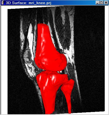
How do I display image slices together with 3D models?
3D-DOCTOR can easily displays the image slices together with your 3D models. If you have a surface model display window open, use the View/Image Planes command to turn on the image plane display. You can use the View/Image Settings command to change the transparent and opaque properties and individual plane display status.
This is an example of knee bone model displayed together with the original MRI image:
Back to Top
How do I control the animation of objects separately?
The View/Animation Control command allows you to define and control the animation sequence and movement for each object.
The View/Object Control command allows you to hide, or show objects with certain display settings during the animation process.
To define the movement of an object in the animation, first select the object from the Object List and then enter the following parameters:
- Rotate (in degrees): The X, Y, and Z are the increments in degree that changes the three angles that control the rotation of the object at each frame. The X is for the angle that rotates counterclockwise around the X-axis while Y and Z are similar for the Y and Z-axis respectively.
- Move By: The increments for location shifting along the X, Y and Z-axis at each frame.
- Scale: The increments for the scaling factors along the X, Y and Z-axis at each frame .
- Steps: This defines the number of steps to be used in a loop for the above movement parameters. For example, if Rotate has 10 steps and the X increment is 5, then the object will be rotated 10 times, each time the angle is the current angle plus 5 degrees. The next parameter controls how the loop continues to the next loop .
- Loop Control: Two options can be used: “Return to Starting Point” and “Reverse Direction”. When the “Return to Starting Point” is used, the object will jump back to its initial position and shape when each loop ends. When “Reverse Direction” is used, the increment will become decrement at the end of each loop and the object will move back in reversed direction .
The viewing angle controls the change of the three angles by using the three increments. The viewing angle controls the global display.
You can use the “Test” button to preview the animation. Click here to see an example. (The animation is courtesy of G. Martins, Confocal Microscope and 3-D Imaging Facility, SUNY at Buffalo.)
Back to Top
How do I create a video of flying through an object?
With 3D-DOCTOR, you can create a fly through video (AVI file)
for 3D objects.
You first create or load some 3D objects in to 3D-DOCTOR, start the
"Animation/CreateMovie" process, then use the mouse to fly through the
object while recording the AVI file.
The left mouse rotates the object, the middle mouse wheel
moves into or out the object, and the right mouse moves the view port.
Back to Top
What platforms
(Operating Systems) does 3D-DOCTOR run on?
3D-DOCTOR runs on PC running Windows, including Windows 7/8/10, or newer versions of Windows.
3D-DOCTOR has native Windows 64-bit version that runs on XP 64-bit, Vista and Windows 7 64-bit. The 64-bit version uses more than 4GB of system memory and is capable of processing very large size images.
Back to Top
What are the licensing options? USB Dongle, Software key, etc.
The following table shows the licensing options available for 3D-DOCTOR:
| License Type | Installation Method | Validation | Multiple PCs |
| USB Key (Dongle), delivered by mail. | Plug into a USB port | Not needed | Runs on one PC at a time but can move easily between PCs |
| Software-Key, delivered by email. | license key file by email | Yes, validation is required to receive the license key file | Only on a single PC. Requires revalidation when transferring license to a different PC. |
| Network Floating License (USB Net Key), delivered by mail | Plug into a USB port on a server | Not needed | Runs on multiple PCs at the same time based on the number of licenses purchased |
Does 3D-DOCTOR run on a Unix system?
Not directly. However, it could work on a Unix machine if a Windows binary emulator is installed.
Back to Top
Does 3D-DOCTOR run on a Linux system?
The current version does not run directly on a Linux system. There are Windows binary emulators available but we have not tested them for compatibility. We are looking into the possibility of creating a Linux version for a future release.
Back to TopDoes 3D-DOCTOR run on a Macintosh system?
No native MAC version yet. Some users have used 3D-DOCTOR on a MAC through a Windows emulator.
Back to Top
What's a reasonable set up for my PC to run 3D-DOCTOR?
3D-DOCTOR can pretty much run on any standard Windows-PC. Faster CPU, plenty of system memory, high performance hard disk drive and a good video board will certainly improve the performance.
Back to Top
What's the ideal hardware set up to run 3D-DOCTOR?
To improve your computer performance running 3D-DOCTOR, one or all of the following can be done:
- Add maximum RAM to your PC
- Get the fastest CPU (higher CPU clock speed for each CPU core)
- Have a fast video display board with built-in OpenGL support
- Install high performance and large size hard disk drive
Back to Top
How do I calculate the volume of 3D object in a CT/MRI scan?
Yes. Here are the main steps:
- Open the image using the "New Stack" command or the DICOMDIR file.
- Trace the object boundaries using the "Boundary Editor" or one of the segmentation functions.
- Create surface models using the surface rendering function.
- "Tools/Calculate Volume" to get the volume and surface area calculation.
Able Software is a Solution Partner with SolidWorks. After you have created 3D models using 3D-DOCTOR's "Surface
Rendering", you can export the model using the "STL" (binary)
format. In SolidWorks, use the "File/Open" command with the
option "As Solid Body" to open the file.What format
should I use to export model to SolidWorks?

Because the 3DS file format can not handle 3D model with more
than 65536 vertices, it is best to export your model using the
"Wavefront OBJ" format and then import the model into 3DSMAX.What 3D format
should I use to export model to 3DSMAX?
Yes. You can use 3D-DOCTOR to create models from CT, MRI, or
other volumetric images and use the models in a Finite Element Analysis
software. For example, if you use Hypermesh from Altair for FEA
applications, you can use 3D-DOCTOR's complex surface rendering
function to create models and then export the models to ASCII STL
format. In Hypermesh, use the Import/STL option to import the model for
further meshing and finite element analysis applications. For some FEA packages, you can segment the image and then
export the boundaries to a IGES file using the "File/Export Boundary"
command. The boundary IGES file can then be imported to a FEA for
meshing and finite element analysis applications.Can I use 3D-DOCTOR
to create models for finite element analysis (FEA)?
Back to Top
Yes. Use 3D-DOCTOR's surface rendering functions to create the
model and then export to a format supported by the rapid prototyping or
3D printing machine. For 3D monochrome printing, the binary STL is supported by
most systems. For 3D color printing, the VRML format is commonly used.Can I create 3D
models for rapid prototyping/3D printing using 3D-DOCTOR?
Back to Top
Use the Edit/Calibration command and enter
the thickness and unit. The thickness is actually the slice thickness
plus the distance/gap between slices.How do I
define slice thickness?
Back to Top
Yes. See the 3D-DOCTOR tutorial
for step by step instructions.Can I reslice my
3D image along another axis?
Back to Top
This is can be done quite easily. Resliced volume
images make 3D measurement of certain objects more accurate. It works
as if you are allowed to rotate your CT or MRI scanner around the
patient for the perfect imaging position, but a lot easier. Open your image and then select the Image/Reslice/Reslice
Volume command. Enter the 3D angle you want to use and click
"Start" to create the resliced image in a few seconds. How do I
reslice a 3D CT/MRI image at an arbitrary angle?
Back to Top
Yes. See the 3D-DOCTOR tutorial
for step by step instructions. For interactive image registration, click
here.Can I register
two 3D images for fusion or comparison?
Back to Top
Can I automatically align the slices in a 3D image?
Yes. See the 3D-DOCTOR tutorial for step by step instructions.
Back to Top
How do I manually align image slices?
This can be done using the "Image/Align Slices" command. See 3D-DOCTOR tutorial video for step by step instructions.
Back to Top
How do I reslice an image with uneven spacing between slices?
When your 3D image has uneven slice thickness or variable spacing between slices, it needs to be corrected to have accurate 3D rendering and quantitative analysis. 3D-DOCTOR's Reslice (Image Menu) command allows you to enter the uneven slice thickness and spacing values between all slices and creates a new image with even slice thickness and spacing between slices using an optimal interpolation algorithm.
The following are the steps needed to reslice an image:
Step 1. Open the image that has uneven spacing using the File/Open command. If the slices are in separate files and you have not put them into a stack, use File/New Stack to do so and then open it.
Step 2. Select the Image/Reslice/Reslice command. The Image Reslice dialog box appears that lists the slice thickness values between all slices. Edit the slice thickness values if necessary to reflect the exact uneven spacing between slices. The New Thickness is the desired slice thickness and spacing between all slices for the new image. A smaller value will add more slices while a bigger value reduces the number of slices in the resliced image.
Step 3. Enter a new image file name for the output image and click OK to start. Once the process is finished, you can close the current image and use File/Open to open the new image for 3D analysis and rendering.
Back to Top
How do I put a stack of 2D image slices into a volume?
The following are the steps needed to create a stack list which can be used as if it is a single image file.
Step 1. Select File/New Stack. The New Stack definition dialog box will appear.
Step 2. Use the "Add Files" button to add files to the stack list. A file open dialog box is used to browse and get file names.
The file open dialog box supports multiple file name selections so you can add several files in one group. Make sure the order of the files added correspond to the order the image planes are acquired. The "Delete" button allows you to delete a file from the current list. Select a file from the list first and then press the "Delete" button.
If you need to preview an image file added in the list, select the file name in the list and then press the "Preview" button. The image will be displayed in the preview window. If the image can not be previewed, then you may have a problem with the file or the file format used. You may have to use 3D-DOCTOR's File/Raw Image File Import function to configure the file first.
Step 3. Once the files are added to the
list, you can save the list to an image list file. You can also open an
existing list of files for editing by pressing the “Open List” button.
Step 4. Click OK to open the 3D image list you just created. In the future, you can use the File/Open command to open the list file directly. All files stored in the list will be treated as an image plane within the 3D image.
Back to Top
Is there a scripting tool in 3D-DOCTOR for customized programs?
Yes, 3D-DOCTOR provides 3DBasic, a Basic-like scripting for writing customized programs. 3DBasic uses Basic syntax and no strong programming background is needed.
3D-DOCTOR's online help and tutorial include many 3DBasic examples for doing different tasks.
Back to Top
Can I run 3DBasic script outside 3D-DOCTOR?
Yes. 3DBasic can be used as a batch script in the command line form. 3DBasic can also be run within 3D-DOCTOR together with the displays. 3DBasic interpreter is implemented as part of 3D-DOCTOR.
Back to Top
What does segmentation do?
Image segmentation traces object boundaries that are necessary for creating 3D surface models and volume rendering. You can experiment with the different segmentation methods to find the best one for your image.
The Auto Segment command works well for images with distinguishable texture, color and contrast between objects. It is very simple to use and you only need to enter a number for how many objects you'd like 3D-DOCTOR to detect. That's all you need to do to generate object boundaries and create a quick 3D view of your image.
The Interactive Segmentation method is best for objects with uniform intensity level. The Segment Object which uses texture defined by training area can be used to handle complex objects. For all segmentation methods, a region of interest (ROI) should be defined for more accurate boundary extraction.
Back to Top
Can I generate object boundaries manually?
Yes. See the 3D-DOCTOR tutorial for step by step instructions.
Back to Top
How do I create a 24-bit
RGB color image from a grayscale image?
You can create a color image from 2 or 3 grayscale images (both 8-bit or 16-bit) using the Image/Image Fusion/Color Fusion function. Each grayscale image is used as one color component, therefore, 3 images will make the red, green, and blue components to form a RGB image. Some users have created color images by combining CT and MRI images. You can use Image/Registration to register the images if they are in different orientation or scale.
Back to Top
How do I combine image slices to create a fusion?
The Image Fusion/Plane Fusion command combines all image planes or slices from a currently displayed image stack into a single slice image. The Image Plane Fusion dialog box appears. The slices can be fused using one of the following methods:
Minimum: This method checks all pixels at each pixel location of all image planes and keeps the smallest value for the final fusion image.
Average: This method adds up all pixels at each pixel location of all image planes and calculates the average value for the final fusion image.
Maximum: This method checks all pixels at each pixel location of all image planes and keeps the biggest value for the final fusion image.
Once the fusion image is successfully created, use the File/Save/Save Image As command to save it to a file.
Back to Top
How do I use color image classification and segmentation?
You can use 3D Rendering/Segment Object directly on a color image to extract object boundaries. Or you can group the colors into a smaller number of color classes using the Image/Processing/Color Classification function and then 3D Rendering/Segment Object to get the boundaries.
To do the classification, open your color image file first (if multiple slices, use File/New Stack to put them together) and use the Image/Processing/Color Classification function. Enter the number of classes as the number of color groups the image has and use the default iteration number. A classified image is saved to a file. Open this new file and use the 3D Rendering/Segment Object command to get the object boundaries.
If you want to use the 3D Rendering/Interactive Segment command, you need to convert the color image to a grayscale image and then segment.
Back to Top
How to convert SLC format files into STL format in 3D-DOCTOR software?
SLC file is a stack of slices of a model. SLC format is used
by many software packages, including JewelCAD, 3D Systems and others.
Use the following steps to convert the SLC file to STL file for rapid
prototyping applications:
Step 1. Start 3D-DOCTOR.
Step 2. File/New Workspace to get a blank window
Step 3. File/Boundary/Import Boundary to open the SLC file
Step 4. Use Edit/Calibration to adjust the values. Change them to 1 if
you like.
Step 5. 3D Rendering/Surface Rendering/Simple Surface to create a 3D
Model
Step 6. File/Export Model to save to a STL (ASCII or Binary) file.
How to move 3D-DOCTOR project files to a new location?
Each project contains 2 types of files, the project data file itself and the image files. If your image slices are stored in separate files, such as DICOM, you'll have both the stack list file (*.lst) and the DICOM slice files. Both the project file and the stack list file keep exact file path to the image slices.
To move a project to a new location, you can first create a folder at the new location. Then copy the project file (*.prj), the stack list file (*.lst) and the image data files (DICOM, TIFF, JPEG, PNG, BMP, etc) to the new folder. If some of the files are in folders, move all of them to the new folder so 3D-DOCTOR can find all the files when you open the project at the new location.
What is deconvolution?
Image deconvolution is used to remove or reduce degradations caused in the imaging process. These include the blurring introduced by optical systems and by image motion, as well as noise due to electronic and photometric sources. 3D-DOCTOR provides two types of deconvolution to restore degraded 3D images, one is a Fast Nearest Neighbor deconvolution and the other is an iterative Maximum Entropy deconvolution method.
Back to Top
What is a point spread function (PSF)?
A point spread function is the impulse response function of an imaging system, which makes image restoration possible by deconvolution.
A PSF of an imaging system can be obtained by imaging a point light source or it can be estimated theoretically. 3D-DOCTOR has a function to create a synthetic PSF when one is not available.
Back to Top
How do I create an image mosaic using 3D-DOCTOR?
Creating an image mosaic is easy with the Image/Mosaic command. This command can be used to merge image slices from a 3D volume image or a 2D image to create an image mosaic.
The following are the steps:
Step 1. Prepare your images: If the images to be combined are not the same type, for example, 8-bit grayscale and 16-bit grayscale, you need to use the image conversion commands to convert them to the same image type.
Step 2. Start the Image/Mosaic command. When the Image Mosaic dialog box appears, define the mosaic matrix and the names of the image files to be used for the mosaic. Click the "Create" button and the generated mosaic image will be displayed. Save the image to a file or continue for additional processing.
Back to Top
How do I compare a pair of
CT/MRI images using 3D-DOCTOR?
3D-DOCTOR provides many different ways to compare 2 or more 3D images (CT, MRI, or microscopy), including image registration, image color fusion, image fusion by arithmetic combination, 3D model combination, and object boundary combination.
The following explains each type of comparison and their benefits:
-
Image Registration: If 2 or more images are in a different orientation and size, you can define 4 or more control points in 3D-DOCTOR and register them against a base image. When images are properly registered, you can compare them using image fusion and other functions.
-
Image Color Fusion: For 2 or 3 images, use Image/Color Fusion to create a RGB true color image, where each image is used as a color component in the final RGB color image. Differences between images will be shown clearly in the color space as the combined colors.
-
Image Fusion Using Arithmetic Algorithms: This function combines two 3D images to create a new fusion image using one of the following operators: Add, Subtract, And, Or, Transparency, Max, Min, and others.
-
Combine Object Boundaries: Object boundaries from another image can be easily imported to compare to the current image to show the difference in terms of size, area, and location. They can also be used together in 3D rendering.
-
Combine 3D Models: 3D models created from multiple images can be displayed together to show differences in terms of size, location, and material characteristics.
Back to Top
How do I create object report for density measurement?
Once you have defined object boundaries for a 3D image, select Edit/Object Report command to calculate the pixel density measurements from the 3D image. The measurements include number of pixels, min and max pixel density, and mean and variance.
If you have entered calibration parameters for image pixel density, the calibrated value will be used in the calculation.
If your image is color image, then the calculation will be done for all color channels. You can use the results for color analysis.
The data can be used in a spread sheet program for plotting or pasted directly into your report or paper.
Back to Top
How do I get object size analysis report?
With 3D-DOCTOR, you can generate boundaries or contours for multiple objects, or import boundaries from other programs. The boundaries can then be used to create a statistical report for the size, area, count, and other parameters of all objects using the Edit/Boundary Report command for quantitative analysis.
The data can be used in a spread sheet program for plotting or pasted directly into your report or paper.
Back to Top
How do I calculate the histogram of 3D objects?
Once you have defined boundaries for the objects in a 3D image, select Edit/Object Histogram command to calculate the histogram from the 3D image.
If you have entered calibration parameters for image pixel density, the calibrated value will also be included in the histogram output.
If your image is color image, then the histograms for all color channels will be calculated. You can use the histogram data for color analysis.
The data can be used in a spread sheet program for plotting or pasted directly into your report or paper.
Back to Top
How do I get 3D measurements on an object, for example, along the airway?
3D measurements such as area and perimeter at a location on a 3D object, for example, along the airway, can be made using the Surface Contours command. The following process is suggested and please refer to the 3D-DOCTOR User's Manual for details on the functions:
Step 1. Create one or more 3D models to be measured from your CT or MRI image using the Surface Rendering command.
Step 2. Select Process/Surface Contours command to generate surface contours. A contour is calculated as the intersection between the 3D object and a defined cutting plane. Move the cutting plane to each location you need to make the measurement and use the Get Contours button to acquire contours. Repeat this process until you have contours for all locations where measurements are needed. Click the Finish button to exit from the surface contour process.
Step 3. Select Contour Report command to get measurements for all the acquired contours. This command calculates the area, length and center location of all existing surface contours and displays in a report.