3D-DOCTOR Release Notes
- 3D-DOCTOR Major New Release Announced (August, 2012)
- New 3D-DOCTOR 64-bit version for Windows 7 (April, 2011)
-
New Functions for 3D Model, Boundary and DICOM Support (March, 2006)
-
Interactive 3D Image Registration and Enhanced Volume Rendering (Feb. 2006)
-
New Volume Rendering and Improved Surface Modeling (April, 2005)
-
Simplified Image Segmentation and Improved Tomography Reconstruction (April, 2004)
-
Improved DICOM Handling and New Image Classification (Sept. 2003)
-
Fully Automatic 3D Segmentation and Accurate 3D Measurements Are Added (March, 2003)
-
3D-DOCTOR Adds Advanced 3D Animation and More Formats (Feb. 2003)
-
New Version 3.5.020420 Released (April, 2002)
-
3D-DOCTOR 3.5.011004 Released (Oct. 2001)
-
New Version 3.5.20 Available (August, 2001)
-
3D-DOCTOR Version 3.5.11 (June, 2001)
-
3D-DOCTOR New Update (May, 2001)
-
3D-DOCTOR New Version 3.5 Released (April, 2001)
-
3D-DOCTOR New Version 3.0.5 Released (Jan. 2001)
3D-DOCTOR Major New Release Announced
Lexington, MA, USA - August 2, 2012 Able Software LLC., a global leader in 3D medical imaging and modeling software, announced today a release of its US FDA 510k cleared 3D-DOCTOR software. This new release delivers much refined and simplified user interface and improved 3D rendering and modeling performance. 3D-DOCTOR™ supports both grayscale and color images stored in DICOM, TIFF, Interfile, GIF, JPEG, PNG, BMP, PGM, RAW or other image file formats. 3D-DOCTOR creates 3D surface models and volume rendering from 2D cross-section images in real time on your PC. You can export the surface models to STL (ASCII and Binary), DXF, IGES, 3DS, OBJ, VRML, PLY, XYZ and other formats for surgical planning, simulation, quantitative analysis and rapid prototyping applications. 3D-DOCTOR is cleared by the US FDA (US Food and Drug Administration 510K clearance) for medical imaging and 3D visualization applications. It has been named the Top 3D Imaging Software by Scientific Computing & Instrumentation Magazine in the Year 2002 and Year 2000 Annual Technology Leaders Issue. Highlights of the new release include:
- Refined and simplified user interface, with a total redesign of the tool buttons. The tool bars now use a large size with brighter graphics design so they can be located and used easily.
- Image and 3D rendering display windows no longer use the traditional scrollbars so more display space is used for image content. Image panning and scrolling is now done easily with the mouse.
- Reorganization of the user menu items. Related functions are grouped together and in the order they are used to finish a certain task.
- Improved international support, for the Japanese and Chinese user interface. Support to other languages are being added.
- The online help has been improved significantly with added tutorials and links to tutorial video clips.
- Performance improvements are implemented to increase the speed of 3D surface rendering and mesh model generation.
New 3D-DOCTOR 64-bit version for Windows 7 (April, 2011)
A new release of 3D-DOCTOR is now available. This new release includes:
1. The 64-bit version of 3D-DOCTOR is fully compatible with Windows 7. The 32-bit version is updated as well to support all Windows platforms, including Windows XP, Vista and 7.
2. Enhanced 3D surface rendering algorithms to generate high quality surface model output.
3. Improved DICOM reader to handle variety of DICOM and DICOMDIR files.
4. Other minor improvements and bug fixes.
New Interactive Image Slice Alignment Tool (Oct. 2008)
The main addition to this version is the new "Interactive Image Slice Alignment" tool ("Image/Align Slices"). This new tool replaces the old "Image Alignment Using Markers" tool. A new algorithm for fully automatic image alignment is implemented for the "Image/Auto Alignment" function. With this new algorithm, both image rotation and shifting can be corrected automatically. It supports both grayscale and color images.
The improved "Interactive Segmentation" function now supports both
grayscale image and 24-bit color images. To
segment a 24-bit color image, there are 3 slider bars for adjusting the thresholds for the 3 color channels (red, green and blue).
A "Reverse" option is added to allow the segmentation of pixel outside
the thresholds range. For example, if the specified threshold is 150 to
190 and the "Reverse" box is checked, then pixels in the range of (0,
149) and (191, 255) will be segmented.
A tutorial video for using the image alignment tool is available at
The commands under the Image/Align Slices submenu allow you to move or rotate image slice around until it is aligned to the neighbor slice.
The image slice alignment should be done first before doing segmentation, 3D rendering or other processing.
The following steps explain how to use the Align Slices commands to align the slices of a multi-plane image:
1. Open the image stack using the File/Open command. You should see two windows, the image plane window and the montage window. If you have not created an image stack list, you can use the “New Stack” command to do so.
2. Select Image/Align Slices/Start Alignment to start the alignment tool. The current image slice is turned transparent and displayed on top of the previous slice. For example, if your current image plane is 55, then image plane 54 is displayed together with 55. Both are displayed transparent. The initial tool is “Move Slice”. Hold down the left mouse button and move the cursor within the image window to move the current image slice around until it is properly aligned with the previous slice.
3. If you need to rotate the image slice, click the right mouse button to bring up the floating popup menu. Select the “Rotate Slice” tool. To rotate the slice, simply hold down the left mouse button and move within the image to rotate. Once the image slice is aligned, release the left mouse button to confirm.
4. Use the F5 and F6 function keys to move to the previous and next plane to continue the alignment process. Repeat Step 2 and 3 to align all image slices. Even though the slices appear to be aligned at this point, the alignment is for display only and the current image stack is not changed. You'll need to follow the next step to save the aligned image stack to a new file for further processing.
5. Once all slices are properly aligned, click the right mouse button to bring up the popup menu and select the “Save Aligned Image” command to save the results to a new image file. The Save As dialog box will appear and you can enter the file name that is going to be used to store the new aligned image. Click the “OK” button to start the alignment process. When the process is finished, use the File/Open command to open the aligned image file for display and processing. The current image stack is not changed during the process.
Image Tilt Correction, 3D Angle Measurement (May, 2008)
This
new version includes the following new functions and improvements:
- A new "Add Folder" option is added to the “New Stack” command. This function will search all files and subfolders within the selected folder for image files and add them to a stack list. It solves the problem where some CT scanners save DICOM files in many subfolders.
- A new 3D angle measurement tool is added to the surface rendering window. Select “Tool/Measure Angle” to start the tool. Click 3 points on a model to get the angle measured.
- New “Image/Tilt Correction” function is implemented to correct gantry tilt image distortion. Some CT image slices (most are in DICOM format) are acquired with a tilted gantry so the slices are not perfectly perpendicular to the main axis. This new function will use the angle stored in the DICOM header to compensate the tilt and generate image slices that are perpendicular to the main axis for segmentation and 3D rendering applications.
- Added “Line Width” attribute for the object boundary display. To change the boundary line display width, use the “Edit/Object Settings” command and then click on the “Line Type” button.
- Enabled editing options for the regions of interest (ROI) created from object boundaries (using the “Edit/ROI/ROI from Boundaries command). ROIs on different image planes can be edited and deleted using the ROI editor.
- Added the “Move Note” function to the “Annotation Editor” to move an existing annotation to a different location.
- The “Delete Node” tool under the “Boundary Editor” has been improved to allow removing nodes continuously. When the “Delete Node” tool is selected, pressing down the left mouse button will change the tool to a node eraser and boundary nodes touched by the eraser will be removed.
- Improved the "Copy Boundary" tool under the “Boundary Editor”. One can draw a selection rectangle to select a group of boundaries and then use the “Control-C” key to copy. The boundaries can be pasted to a different image plane using the “Paste” or “Control-V” key.
- Additional image output file formats are added to the “File/Save Window” command. The window image can now be saved to BMP, TIFF, JPEG, DICOM and other formats.
- The 3D “Volume and Surface Area Calculation” command now uses an area-weighted algorithm to calculate the centroid of a 3D object.
- HTML based online help is now supported in 3D-DOCTOR.
- New image conversion function to convert 1-bit image to 8-bit grayscale.
Details
about downloading and installation are available at
http://www.ablesw.com/3d-doctor/support.html
New Region Growing Based Segmentation (Nov. 2007)
This new version includes the following new functions and improvements:
1. New region growing based segmentation algorithm is implemented for the “Segment Object” command. The new algorithm segments more effectively for soft and tumor tissues by using both texture and edge information from the image. A video tutorial for this function can be watched at: http://www.ablesw.com/3d-doctor/mvsegobj.html
2. The image reslicing functions (Reslicing X/Y) is updated to use a multi-pass algorithm to reduce the system memory usage to handle large size image stack.
3. Updated the image saving and exporting functions to use sequential filenames for image slices.
4. Added the "Notes" function so notes and annotations can be added to the surface file.
5. Some other bug fixes and minor updates, including a STL file import issue with incorrect object display location.
New Image Cropping and Creating Hollow Object (Dec. 2006)
This new version includes the following new functions and improvements:
1. The "Image/Crop ROI (Region of Interest)" command is re-implemented with additional functionalities. The cropping operation can be applied to either inside the regions of interest (ROI) or outside the ROI. The operation can be either a constant color or a linear transformation with user-defined parameters.
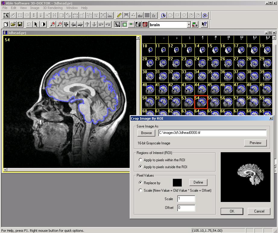
Regions of Interest can be drawn using the "Edit/ROI Editor" (one applied to all planes) or generated from CURRENT object boundaries (each image plane has its own ROI) using the "Edit/ROI/ROI By Boundaries" command. The ROIs are often used together with the segmentation functions.
This function is used to remove part of the image or change some portions for simulation or comparison.
2. A new function "Edit/Boundary Process/Hollow Object" is implemented to create hollow object boundaries (donut shape). The hollow boundaries will therefore create a shell instead of a solid core for the object. For objects with thin walls, you can use the "Interactive Segmentation" to trace solid boundaries (single outline for the object) first and then use this new function to create a hollow object. See attached image. The thickness can be specified in pixel unit.
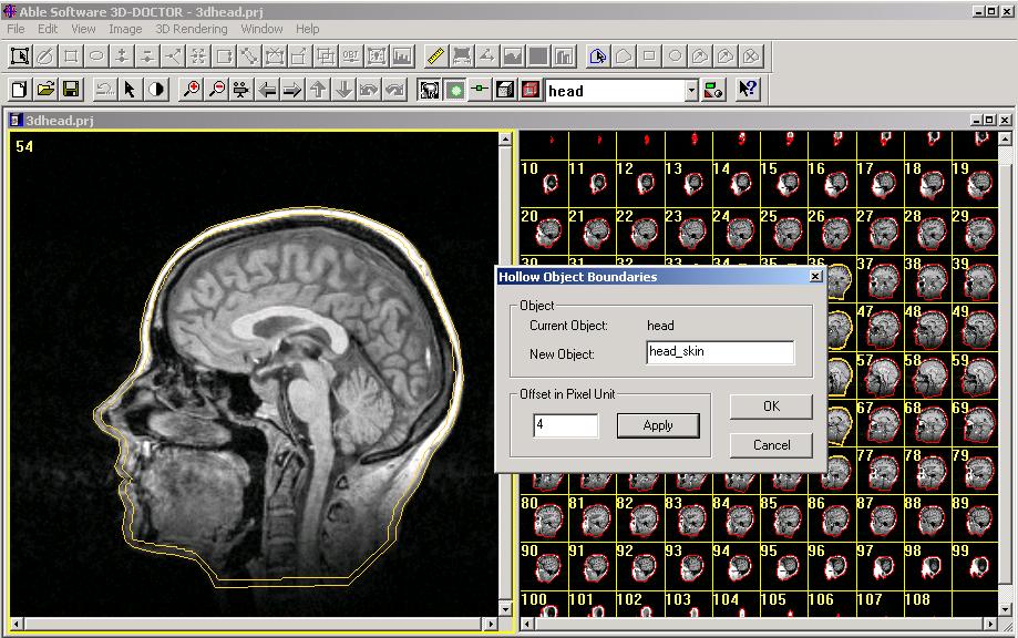
The hollow boundaries work well for objects oriented perpendicular to the image planes. However, if you see holes added to your 3D object when doing a 3D surface rendering, you should use the "Boundary Editor" to either make the inside boundaries smaller or simply delete the inside boundaries to restore the surface area on these image planes.
New Functions for Splitting 3D Objects (Nov. 2006)
A
new release of 3D-DOCTOR is now available at our website for download.
This new version includes the following new functions, user interface
improvements and updates:
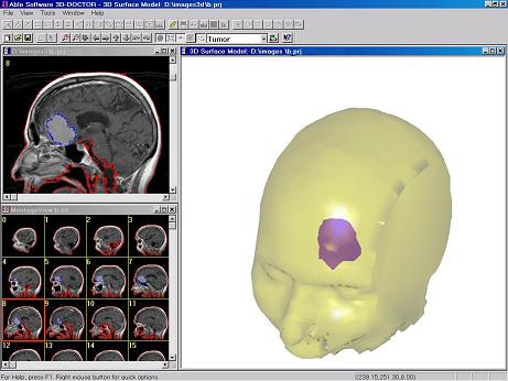
1. For surface rendering
display, a new function is implemented to color the backside (inside of
a surface model) of a model with a different color. The option is
turned on through the "View/Two-Sided Lighting" command. This option
works with the "Tools/Split Object" command to show the inside of a
model when a portion is cut off.
To split a model, first create the model using the "Surface Rendering"
command. Start the "Tool/Cutting Plane" command to show the cutting
plane. The normal of the cutting plane is always the viewing direction
(perpendicular to the screen). Use the "left mouse" or the LEFT/RIGHT
key on the keyboard to rotate the object. Use the "middle mouse wheel"
or the UP/DOWN key to adjust the "cutting plane" location.
You can then use the "Split Object" command to cut off the part in
front of the cutting plane. The split object is a new object and the
original object is hidden. You can use the "View/Object" command to
change the display properties or delete an object.
To change the backside color of a model, start the "View/Object"
command. Click on the "Color" field or highlight the object then the
"Color" button. Choose the "Backside Color" tab to define the color.
The backside color can be turned on/off using the "View/Two-sided
Lighting" function.
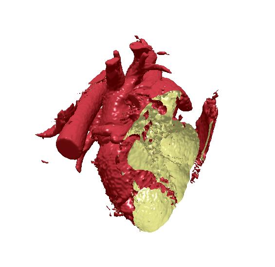
(See the attached image, a split heart model created from a CT scan).
2. The Image Information command has added a display of Image Number
for the current image slice. This is specific to DICOM images. If your
image is not a DICOM, the image plane number is displayed.
3. For the 3D measurement tool ("Tools/Measure" on the object surface),
the Markers are made bigger in the display to be more visible.
4. The "Image/Crop Film" command is improved for keyboard input. When
the "Enter" key is pressed, the "Update" function is called instead of
starting the cropping process.
5. The PLY (3D polygon) file import/export has been implemented.
6. Optimized the volume rendering algorithm to make it faster.
3D-DOCTOR Adds New Functions for Image Import
(Sept. 2006) This new version includes the following new functions, user interface improvements and updates:
Display and Printing
-
The new “View/Negate” command is implemented for the Image Plane view and the volume view to reverse the display of grayscale polarity.
-
The “View/Overlay/ Neighbor Boundary Boundaries” command has a new "Current Object Only" option. When this option is checked, only the boundaries of the current object is displayed. Otherwise, the boundaries of all currently “ON” objects are displayed.
-
Option to select a printer is added to the “Print Windows” and “Print Screen” commands.
Image File Handling
-
For the “File/Save Image As” command, an option is added to save image planes to separate TIFF files.
-
Raw Image Import now supports raw image files with signed pixels. Both 8-bit and 16-bit signed (with negative pixel values) and unsigned raw image files can be imported into 3D-DOCTOR for processing.
-
Import for raw image file in ASCII text format is implemented for the “Raw Image Import” command.
-
Support for 32-bit TIFF and BMP images has been added. 32-bit image files can now be opened directly.
Boundary Editor
A new option to move a group of boundaries within a selection rectangle is implemented in the Boundary Editor. To move a group of boundaries, start the “Boundary Editor” and switch to the “Move Boundary” mode. Hold down the SHIFT-key and the LEFT mouse button to draw a selection rectangle around the boundaries to be moved, then hold down the LEFT mouse button to move.
New Functions for 3D Model, Boundary and DICOM Support
(March 2006) This new version includes the following new functions, user interface improvements and updates:
Object and Boundary
1. New interface for the Object Settings command. The object names and
status can now be changed more easily.
2. Boundary Editor: A new cursor is used to indicate if the "Snap to Edges" tracing mode is ON or OFF.
3. Copy Boundaries: A new option to copy boundaries within a selected rectangle to the previous or next image slice is implemented. To do this, start the Boundary Editor, hold down the SHIFT key and the left mouse to draw a rectangle, then right click to bring up the boundary editor menu, then select "Copy to Previous" to copy.
4. Boundary Process/Scale: This command allows you to scale and shift boundaries. It's normally used to adjust/align boundaries when they are created elsewhere and imported to use with a different image.
5. The boundary file (*.bnd) now supports multiple objects. You can use it to export and import boundary data with one or more objects. Note: When exporting boundary data to use on another image, the "Apply Calibration" option should not be used.
3D Model/Surface Rendering
1. Under the Tools menu, there are three new functions: "Select", "New
Object" and "Delete". When an object has multiple parts that are
disconnected, you can use the "Select" tool to pick a part. The
selection is then highlighted. Use the "New Object" command to set the
selected part as a new object. Or delete the selection using the
"Delete" command.
2. Object Property/Display Order: When multiple objects are displayed together, some objects can be blocked by other objects and become invisible. If this happens, you can adjust the order in which the objects are displayed by using the "Move Up" and "Move Down" buttons from the Object Property dialog box. An object that's inside of other objects should normally be moved to the top of the object list while an outside object should stay at the bottom of the list.
3. Object Property/Opacity: The new opacity field is added to the Object Property dialog box. The values used should be between 0 and 1. Higher value means more opaque while lower value means more transparent.
DICOM Files
A new "Open Stack" option is added when opening a DICOMDIR file that
has more than one image series. With this option, you can select an
image series and open the image stack directly. A stack list is created
in this process so the "New Stack" command is not needed in this case.
Image Processing and User Interface
1. Implemented a new algorithm for the Reslice X and Relsice Y
functions. They will process much faster than the previous versions.
The functions now support 24-bit RGB image as well.
2. When adjusting contrast or doing interactive segmentation, you can now use the keyboard arrow keys to adjust the slider bar. The LEFT/UP key decreases the low-end value by 1 each time it's clicked while the RIGHT/DOWN key increases the value by 1. When the SHIFT key is pressed, the arrow keys will work on the high-end value.
Interactive 3D Image Registration and Enhanced Volume Rendering (Feb. 2006)
This
new version includes the following new functions, user interface
improvements and updates:
- Image Registration: A new interactive registration command is implemented to register a source image against a target image of different or same modality. The Register Image command displays the two images together in 3D. You can then adjust the orientation, location and scale until the two images are registered. A new registered image is created and can be used for fusion and 3D modeling applications. Details at http://www.ablesw.com/3d-doctor/regist.html. When the target is the same as the source image, the function can be used to rotate and adjust image.
- Opacity for Volume Rendering: A new function to let you adjust the opacity curves (Density and Gradient) used in Volume Rendering. Each curve defines the corresponding opacity of the density/gradient values. By adjusting the curve, you can remove soft tissue or tissue within a density range from the rendering. To change the curve, first click the left mouse on the curve to show the points. Click the left mouse on the curve again to add a point. Hold down the left mouse to move a point up and down. Click the right mouse on a point to delete. Click “Apply” to update the rendering. Examples at http://www.ablesw.com/3d-doctor/volume.html
- Complex Surface Rendering: Added options to set the triangle denseness parameters to control the number of surface polygons and their sizes generated from surface rendering. 1 is the smallest value allowed which will use the maximum number of surface polygons. Larger value will decrease the density and uses less system resource to process.
- Object Animation: Additional object animation options, such as opaque, transparent, wireframe and texture have been added. The tissue display properties can be switched between transparent, opaque, wire frame and with texture map during the animation. Objects can be moved, scaled, hidden or made visible in the animation process.
- Animate Image Planes is now available for the surface rendering window.
- Added mouse wheel support for zooming in and out. For the surface rendering window, the right mouse is now used to move the viewport.
- Boundary Editor: A new “Snap To Edge” option is implemented. When it’s turned ON, the software will try to follow the edges of an object while the cursor moves. Click the left mouse button to confirm.
- The Image Info command has added fields to enter patient information so they can be saved to DICOM files.
- The "3D Wizard" auto start can be turned on and off using the “File/Auto 3D Wizard” command.
Object Animation and Rendering of Sub-Volume (Nov. 2005)
This new version includes the following new functions, user interface improvements and other updates:
Volume
Rendering
- A new function to select a range of slices to be used in Volume Rendering. Once a volume rendering is created, use the “View/Slice Range” to enter the range. Use this function to create a rendering of a portion within the volume.
- New functions to hide and show slices. Use the “View/Slices/Hide Slices” or “Show Slices” to hide or show slices at the front or the back of the volume. The orientation can be set using the “Front to Back” command. When it’s checked, the slices at the front of the volume are used in the operation.
- “View/All Slices” command: reset selection to use all slices in volume rendering.
- Added mouse wheel support for zooming in and out control.
Surface
Rendering
- New “Object Animation” function. This command allows you to create an animation sequence to hide or show selected objects during the animation.
- Improved 3D surface model display with the new perspective projection support.
- Added mouse wheel support for zooming in and out control.
Image
View
- New function “View/Full Resolution” to create full resolution display of side and front views when using the “All Views” command.
- A new “Flip Vertical” option is added to reverse the top and bottom orientation of the side views.
- The 3D Wizard is improved to better reflect the processing status.
- Mouse wheel supported for scrolling through image planes
- Improved the algorithm used by the “Segment Object” function for more robust segmentation.
DICOM
& Files
- Added additional DICOM tags in the 3D-DOCTOR exported DICOM files so they are more compatible with other programs. To export a stack list or a 3D TIFF file, you can use the “File/Save Image As” function. Make sure the export file name has the “.DCM” extension (DICOM) and select “All Planes” or a range of image planes to save. For previously exported DICOM files, you can open the stack list and use the “Save Image As” to create new DICOM files with the additional tags.
- For the “New Stack” command, a new option to "Split Image Series" is added so you can turn on or off the check. This is used to handle DICOM files that store several series in a single image set.
- For the “New Stack” command, we now use the folder name as the default stack list file name.
- Updated the 3D VRML export function to be more compatible.
A Note About Animation and Create Movie
When using the “Full Frames (Uncompressed)” encoding to create an animation, you may get a very large size movie (AVI) file. There are several things you can do to reduce the file size:
- Before you start the animation, reduce the window size. The smaller the window, the less storage it takes.
- Use a compression-based encoding. For example, using the “Microsoft Video 1” encoding can reduce the size significantly. But be careful not to choose one that’s not installed on your machine.
Texture Support and Improved 3D Visualization (Oct. 2005)
This new version includes the following new functions, user interface improvements and other updates:
Surface Rendering
- The 3D surface model rendering now supports the use of a texture image as the skin for display. With this feature, you can create a more realistic rendering by using the texture image from real tissues. To use texture display, first find an image and crop a small section from it and save it to a JPEG or BMP file. At the surface rendering window, start the “View/Object” command. When the dialog box appears, select an object and click the “Texture” button. You’ll be prompted to enter the texture image file name to load. Once it’s loaded, it’ll be automatically applied in the display. This may take some time if your model has a large number of triangles. Also, smaller texture image will help the performance. The texture use can be turned on and off for each object.
- For surface rendering, the use of the color and lighting model have been improved in this version. A new “Pick Color” button is implemented in addition to the sliders for adjusting object color properties.
- The back surface is now visible and displayed after a model is split or cropped using the “Split Object” or the “Crop Object” command.
- Improved the handling of 3D rotation. A new algorithm is implemented to make smooth 3D rotation when using the left mouse button to drag. The right mouse button controls the zoom in and zoom out functions.
- Clicking the left mouse on a surface model automatically displays the image plane number (when available). This makes it easier to check surface irregularities and their locations.
- A new “Clear Measure” command is added under the “Tools” to remove the currently entered measurement lines before starting a new measurement. You can also use the “Escape” key to do this.
Volume Rendering
- A new command “Lighting” is added under the “View” menu. Use this command is turn on and off the use of the lighting effect.
- ROIs (regions of interest) are supported for the “Direct Volume Rendering” command.
Other updates
- Updated the STL ASCII export so the file is more compatible with other software packages.
- Improved the “Contrast Adjustment” interface. Added a "Previous" button to recover previous settings.
- Added volume calculation field in the “Object Report” command. This volume is calculated using the total number of voxels within an object and the size of a voxel defined using the “Calibration” command.
- Removed the window border & scroll bar from the image capture when creating a movie (AVI) file with the “Create Movie” command.
- Localized user interface for Japanese and Chinese language support. If you are running a Japanese or Chinese Windows OS, 3D-DOCTOR will automatically display the localized user interface.
- A special version of 3D-DOCTOR with stereo view support for the volume rendering is now available. This version is distributed exclusively through Synthosys Inc., a 3D stereo system manufacture and a 3D-DOCTOR reseller.
New Volume Rendering and Improved Surface Modeling (April, 2005)
This new version includes the following new functions, user interface improvements and other updates:
1. Boundary Tracing: The freehand and piecewise boundary tracing functions are merged into a single function, called "Trace Boundary". In the new “Trace Boundary” mode, you can click the left mouse button to add new line segments to a boundary, same as the “Piecewise Boundary”. If you hold down the left mouse, you can trace the boundary continuously same as using the “Freehand” tracing mode. Release the left mouse to finish the freehand tracing. When the entire boundary is traced, press the “SPACE BAR” or double click within the image window to close and finish the boundary.
2. New Volume Rendering: This function uses a new smooth shading algorithm for volume rendering. Entire image volume, a portion defined by regions of interest (ROI), or image portions defined by object boundaries can be used for volume rendering. A volume can be rendered in one of the 4 ways:
-
Grayscale with Opaque Voxels: Image voxels are treated as opaque and ray traced and shaded using grayscale values.
-
Grayscale with Transparent Voxels: Voxels are treated as transparent and ray traced to create 3D rendering.
-
Color with Opaque Voxels: Color shading is applied on opaque voxels in volume rendering.
-
Color with Transparent Voxels: All voxels are treated as transparent in the ray-tracing process and color shading is applied. Colors can be changed interactively.
Some sample volume rendering images can be seen at:
http://www.ablesw.com/3d-doctor/volume.html
The previous volume rendering is now called “Direct Volume” with all the functions unchanged.
3. A “DICOMDIR” file can now be opened directly using the “File/Open” command. A stack list is automatically created in the process. You can also use the “New Stack” command to create a stack list from a DICOMDIR file.
4. The “Crop Film” command is improved to allow going back to the image window to zoom in and out to check the cropping template settings.
5. Updated the “Zoom Out” function for the image plane window to display the full image more easily.
6. The “Annotation Editor” now uses the color defined by the “Set Font” command. In previous version, it uses the same color as the object it belongs to.
7. Additional options to the “Boundary Editor/Delete Boundary”: While in boundary editing mode, you can draw a selection rectangle by holding down both the “SHIFT” key and the left mouse button, then “Delete Boundary” to remove all boundaries within the selected region.
8. Improved the performance of both “Simple Surface Rendering” and “Complex Surface Rendering” functions.
9. The Surface file “*.SUF” is now different from previous version. The new version can read previous SUF files. If you have multiple 3D-DOCTOR installations, you should upgrade all PCs with the latest version to avoid any file compatibility issues.
Simplified Image Segmentation and Improved Tomography Reconstruction (April, 2004)
- Improved algorithm for the surface model simplification (Tools/Surface Simplifying) command. To use the command, enter a percentage for the amount of nodes to be reduced and click OK to start the processing. New simplified surface models are added while existing ones are unchanged. Use the View/Objects command to toggle on and off the object display and the display characteristics.
- We have improved the threshold selection bar for the interactive segmentation command. It now uses a single slider to define the threshold range. You can use the mouse to change the min and max threshold, or move the entire range by clicking the cursor in the middle of the slider. Arrow keys combined with the Shift keys can also be used to change the min and max thresholds.
- A new function to uncompress DICOM JPEG images is added under the File menu. Compressed DICOM files cannot be opened directly into 3D-DOCTOR. If you have compressed DICOM files, use the File/Uncompress DICOM command to convert them to uncompressed first. At the dialog box, specify the folder where the compressed DICOM files are located and the folder you want to output the uncompressed DICOM files. Click Start to uncompress them. It is recommended to store the uncompressed files in a separate folder so the series and studies don’t mix together with old files.
- The algorithm for the 3D tomography reconstruction (Image/Reconstruction command) has been refined to provide better quality image reconstruction. The Iterative Back Projection algorithm is working significantly better than the previous versions.
- A new "Add Slices" command is implemented under the Image/Reslice submenu. Now you can add more slices to an image set without having to re-segment the entire image.
- Importing VRML file is supported.
- A new function Tools/Reverse Direction is implemented to reverse surface normal direction for 3D surface models. This command is used to correct the display of some models that have a reversed normal direction (counter clockwise or clockwise).
- For the Regions of Interest (ROI) editor, we have added a new “Adjust ROI” command to modify an existing ROI polygon. While in this editing mode, move the cursor to a ROI, hold down the left mouse button and drag to adjust the ROI polygon.
- Improved user interface for image contrast adjustment.
3D Wizard and New User Interface (March, 2004)
This new version includes the following new functions and improvements:
User Interface:
- A new 3D Wizard function is implemented to assist the 3D model creation process. Once your image is open, you can start the 3D Wizard, and go through the steps to create 3D models from image slices.
- We have improved the display of the image plane view and the montage view and now use a single window to display them. It makes window management easier and quicker to access processing commands. With the “View/All Views” command, you can display the montage view, side view and top view together in a single window.
- A new “Shortcut Keys” function is added under the Edit menu. This command allows you to customize and define shortcut keys to access 3D-DOCTOR functions.
- The tool bars can now be moved around.
DICOM Support:
- DICOM image slice thickness is calculated using image position information when the parameters are available.
- The Image Reslice function uses slice thickness information stored in DICOM images if the slices are not evenly spaced so you can create a new image with even slice thickness.
- Updates to better handle certain types of DICOM images.
- Added more fields for DICOM info display, such as patient birth date, study type and series type, etc.
Segmentation:
- For the Interactive Segmentation, an option to process a range of slices is added to the “Segment All” button. You can segment either the entire image or a selected range of slices.
- The display of regions of interests (ROI) is improved for the Interactive Segmentation to show whether a pixel is inside or outside the regions.
Image:
- Added the new “Move Slices To” command. You can use this command to move slices around within the stack.
- Added the new “Delete Slices” command to delete slices from an image stack.
- Improved the image display to be more consistent between the “Interpolation” and “No Interpolation” mode.
Editing:
- Added a new Merge Boundary function under the boundary editor.
- Improved the Boundary Merge function under the Boundary Process submenu to handle complex boundaries.
- Minor updates for cursors used by the boundary editor.
Simplified DICOM Image Sorting
(Oct. 2003) New updates have been made in 3D-DOCTOR for easier handling of DICOM images and image processing.
1. Improvements in the New Stack command:
a. You can now use the Load List button to read a DICOMDIR file to select a patient-image-series to process. It will load a stack list file as well.
b. We have also added a "Select All" option to the "Add Files" button to add all files to the list and then use 3D-DOCTOR to separate them automatically.
c. A new option "Sort by Name" is added so you can sort non-DICOM images by their file names.
d. A new option "Delete All" is added.
2. Two new "Sort Slices" functions are implemented under the Image Menu: Sort by Image Position and Sort by Image Number. Some MRI image series may not have the correct Image Position stored, in this case, you can use the Sort by Image Number after the image is open.
3. The Image Contrast dialog now displays the Image Grayscale Window (Window Center and Window Width) parameters. The grayscale window is the current visible grayscale range being displayed.
4. Use exact measurement for the Surface Contour Cutting command, instead of using percentage.
5. Added Image Scaling and 3D Location controls to the Image Settings command for the surface rendering window to control the scale and location of image plane display. This allows you to combine a 3D model display with another image that is not the source of the model.
6 For the Boundary Editor, we have added a Smooth Boundary and Smooth Parameter to smooth individual boundary.
7. Added patient info and other related information to the Image Info command.
8. Other fixes related to image registration and fusion.
Improved DICOM Handling and New Image Classification
(Sept. 2003) A new version of 3D-DOCTOR (version 3.5.030920) is now available to currently licensed users from our website.
The following lists new functions and improvements available in this new release:
1. Improved DICOM image import function for better image slice sorting and slice thickness scaling.
2. Added new functions under the Edit/Boundary Process submenu to reverse slice order, flip vertical and flip horizontal for the boundary data.
3. Implemented a new feature that uses different colors to display XYZ points based on their values. This function can be used to display and analyze 3D XYZ points that have values associated with each point location.
4. A new Image/Map Pixel Values command is implemented. This command maps a range of grayscale image values to a new value.
5. Added 3D rotation control using the mouse for the volume rendering window. It works the same way as in the surface rendering window.
6. Added a separate scaling factor for the Z-dimension in the Image/Resize Volume function. When down-sample or up-sample an image, you can keep the number of image slices unchanged while scaling the image’s XY dimension.
7. Added a help feature to most image processing functions that allows you to open the newly created image file when the processing is done.
8. A new function to convert an image from grayscale to 24-bit RGB image is implemented under the Image/Conversion submenu. The pseudo-color palette will be used for the conversion if it’s present.
9. A new interactive image classification function is implemented under the Image menu. This function classifies image voxels into different color groups for segmentation or analysis. It works with both grayscale and color images.
10. Improved the View/Montage View function to support simultaneous views for the side, top and montage view window.
11.
The 3D TIFF file format has been changed to get around the Windows XP
Explorer problem.
12. Enabled Median Filer and Average Filter image smoothing for 24-bit
color images.
13.
Enabled the Sobel Edge detection and the Gradient Magnitude commands to
process 3D
volume images.
14. Improved the interactive marker-based image alignment function to
handle
images with severe distortion between slices.
15.
Improved the Simple Surface Rendering algorithm to better handle
B-Spline
smoothed boundary data.
16.
Added a link in 3DBasic to run batch shell program using 3D-DOCTOR’s
3DBasic
script.
17. Other minor user interface updates and fixes.
Fully Automatic 3D Segmentation and Advanced 3D Measurements Are Added
(March, 2003) A new version of 3D-DOCTOR (version 3.5.030324) is now available to current users from our website. The updated 3D-DOCTOR User’s Manual in PDF format can also be downloaded from our site.
The following lists new functions and improvements for this version:
1. A new fully automatic texture-based 3D segmentation is implemented. This command automatically segments an image and traces the boundaries of a given number of foreground objects. This command works with both color and grayscale images. The segmentation algorithm is texture-based and can separate up to 256 objects. The segmentation command processes within the regions of interest (ROI) if they are present. If you need to define certain regions to be processed instead of the entire image, use the Edit/ROI Tools to define regions of interest before this command is called.
After you call the Auto Segment command, a dialog box appears to ask you to enter the number of objects to be extracted. This number should be determined based on the image. For example, if you see that an image may have 5 objects that show distinguishable texture and color, you can enter 5 to start the segmentation. You can use increase the number to divide objects into smaller regions or decrease the number to combine smaller regions into larger ones.
2. The Image/Color Classification is improved to process both color and grayscale images. The texture information is used for grayscale images while color spectral information is used for color images.
3. New 3D measurement function is implemented to make measurement on a 3D surface model. Call the Tools/Measure command to start the tool. Click on the surface model to enter measurement points and select Tools/Measurement Report to get the results. You can use the Tools/Set To Contour command to turn the measurement curve to a contour for further analysis.
4. New Tools/Digitize Points and Delete Points commands. The commands allow you to interactively digitize 3D points on a 3D surface model. The Point Report command provides a detailed report of the point data.
5. A new 3D object splitting function is added. It’s used to cut a 3D model using a user-defined 3D cutting plane. To cut a 3D object in the 3D surface view window, call the Tools/Cutting Plane command to define the cutting plane location. Use the Up/Down arrow keys to adjust the depth of the cutting plane. You can use the Left/Right keys to check the position of the cutting plane. Once the cutting plane is in the right position, call the Tools/Split Object to cut. The new object is displayed in the window while the display of the original object is turn off. Use the View/Object command to change the display status.
6. A new Crop Object command is implemented to crop a 3D model along the current measurement curve. To crop an object, start the measurement mode first by selecting the Tools/Measure command. Draw the curve on a 3D object and then select Tools/Crop Object to crop. The cropped object is displayed in the window while the original object is turn off. Use the View/Object command to change the display status.
7. Added 3D axes display to the volume view window.
8. Added DICOM sorting options using either Image Position or image number in the New Stack command.
9. Some new functions have been added to 3DBasic: a. SaveProject b. OpenProject c. AutoSegment
10. The Boundary Editor has added a new Rotate Boundary command. While in the Rotate boundary mode, you can click on a boundary rotate it to new orientation.
11. Other minor user interface updates and fixes.
3D-DOCTOR New Version Adds Advanced Animation and More
(Feb. 2003) A new version of 3D-DOCTOR (version 3.5.030212) is now available to current users from our website. The updated 3D-DOCTOR User’s Manual in PDF format can also be downloaded from our site.
The following new functions and improvements are implemented in this version:
1. For the 3D surface model display, a new function is implemented to show image slices together with the models. Image slices can be displayed as opaque or transparent. Individual slices can be turned on or off using the new Image Settings function. This new function can combine display of a 3D model with other images to create a certain display effect. To display image planes, call the View/Image Planes command and then View/Image Settings to adjust the display properties.
2. A new "Shape" option is added to the View/Object command for 3D surface models. This command can be used to change the size, orientation and location of 3D objects. This command is useful when you combine models that are generated from different sources and in different scale. You can use the File/Add/Merge Model command to combine more models and then use this option to adjust their locations and scales.
3. New options to rename and delete object from the surface window are added to the View/Object command.
4. A new Animation Control function for 3D models is implemented. With this command, you can define the animation path of each 3D object with a 9-degree of freedom, including the size, location, orientation and the viewing angle. This function can be used to create 3D simulation and movie.
5. Added Z scale (slice thickness) adjustment to Reslice X/Y functions when slice thickness is not the same as the XY resolution.
6. Improved DICOM image import functions to support to multiple-frame images.
7. When saving a multi-plane 24-bit RGB image to TIFF format, all planes are now saved to a single file.
8. Enabled the Escape key to stop animation process.
9. Improved the 3DS file import function for better handling of colors and objects.
10. Added support to read images in Analyze HDR/IMG format.
3D-DOCTOR New Release (Dec. 2002)
A new version of 3D-DOCTOR (version
3.5.021206) is
now available to current users from our website. The updated 3D-DOCTOR
User’s
Manual in PDF format can also be downloaded from our site.
The following lists new functions and improvements implemented in this version:
-
3D-DOCTOR can now combines the display of image slices with 3D surface models. The new View/Image Planes command turns on/off the display. The new View/Image Settings command is used to change the image plane display properties.
-
A new option under the View/Object function has been implemented for changing the size, orientation and location of individual object.
-
The Create Movie function has been improved for easier AVI file creation and smoother animation. The Start button will automatically start the animation process and capture picture frames into the AVI file.
- New display for the reports, including Object Report, Boundary Report, Contour Report etc. The new interface makes it easier to select a single or multiple row or columns and provides better alignment for data columns.
- New option to save color images in DICOM format.
- New display function to show image plane locations in the 3D surface rendering window.
- The Color Fusion function has been updated to support the background option. One image can be used as the backdrop when fused with other images. For example, when combining a CT and a PET image together, the CT image can be treated as the background and the PET image used in a color channel. Images can also be fused using their reversed polarity (negative image).
- Added support to GIF image format for import.
- New option using overlapped image borders to create seamless image mosaic has been implemented to the Mosaic function. Images without overlapping areas can also be use directly to create an image mosaic.
- A new smoothing image option is added to the interactive segmentation function. This option reduces image noise and generates better quality image boundaries for poor quality images.
- Added support to the Wavefront OBJ file for 3D model import and display.
- Improved the Segment Object command to use image texture more effectively and better performance.
- Added command line processing option to run 3DBAISC scripts directly. You can now write a 3DBASIC script and run it from your own program without the need to start 3D-DOCTOR.
- Improved the Side View and Top View window to display the current image plane, as well as object boundaries.
- For the Calibrations command, a new option is added to simplify the task of calculating XY pixel resolution. Simply enter the size of the display field of view (FDOV) and the calibrations are calculated and applied automatically. This makes calibration easier to do when using images scanned from films or other sources.
- New report function to calculate the area, length and center of generated surface contours.
- Added the prompt for 3DBasic function syntax. New functions added to 3DBasic: RotateImage, NegateImage, SmoothAve, SmoothMed, Sharpen, ReconBackproj, ReconIter.
- A new iterative reconstruction function is added for creating virtual tomography from images taken at regular angles.
- Added support to import the binary SLC file from 3D Systems and create 3D surface models.
New Version 3.5.020420 Released (April, 2002)
We have released a new version of 3D-DOCTOR (version 3.5.020420). It’s available by download from our website. The updated 3D-DOCTOR User’s Manual in PDF format can be downloaded from our site.
This
release includes several new functions and many improvements over
existing
functions:
- For the montage view window, two new viewing options have been added, the side view and the top view. The side view and the top view display a image profile at a specific location and image slice is clearly marked. Similar to the montage window, the image plane marker can be used to scroll between image slices.
- New Image Reslice function that interpolates unevenly spaced image slices and creates a new image with even slice thickness.3D-DOCTOR now supports the open source PNG image format. PNG file format uses a loss-less compression algorithm found in many of the zip programs to achieve maximum compression while maintaining the image quality.
- The support to the Interfile format has been implemented. CT or MRI images stored in the Interfile format can now be opened directly.24-bit RGB color images stored in raw image format can now be imported using the File/Raw Image Import function.
- Color image segmentation has been improved to handle different type of images.3D surface models can now be exported VRML version 2.0.
- New Image Rotation function that rotates an image to a user-defined angle.
- Added Move ROI function to the Regions of Interest Editor.Added IGES format support for boundary data export.
- Added a new interactive image slice alignment function using user defined alignment markers. Image rotation and shifting are applied for image slice alignment. Stretching is only used when more than 4 markers are provided.Improved the smooth surface command for better quality surface decimation.
- Added a new Edit/Object Histogram function to calculate and report object histograms.Added options for object report to do either summery or detail report.
- Updated DICOM import and export functions to be more compatible with other vendors DICOM files.Added functions for point data import and export.Added file save and open commands for object file handling.Other improvements and fixes.
3D-DOCTOR 3.5.011004 Released
(Oct. 2001) A new version of 3D-DOCTOR (version 3.5.011004) has been released. It’s available to all current users at the Able Software website.
This release includes many improvements and new functions:
- New interactive image slice alignment function. Click here to see 3D-DOCTOR tutorial for detailed instructions.
- It is possible to put images of different sizes into a stack list using the File/New Stack command but it can cause problem for image processing and 3D analysis. Because of this we have added an automatic step to check image sizes and correct them to the same size if necessary.
- The Copy Boundary function under the Edit/Boundary Editor menu is improved to combine boundary copy and move together. To copy a boundary in the current image plane when you are in the Copy Boundary mode, move the cursor to a boundary, click and hold down the left mouse button to copy and move the new boundary to a new location.
- Improved the handling of a file path in the stack list file when they are moved to a new folder. The stack list file stores the path to image slices. When you move the image files to a new folder, make sure the list file is in the same folder so 3D-DOCTOR can find them automatically.
- A new Assign Object function under the Edit/Boundary Process menu. This function takes all boundaries in the current object and regroups them into separate new objects based on area-overlapping rules.
- A new View/Overlay/Object Names function to show the object name of a boundary.
- Added automatic boundary rescaling function for the File/Boundary/Import Boundary function. If you import a boundary file created by other sources into 3D-DOCTOR, the scale is automatically checked and adjusted to fit the slice model and avoid missing slices.
- Updated DXF import/export to include 3D point data.
- XYZ cloud points can now be imported for display.
- Updated the Boundary Report function to include center location of boundaries.
- Updated the Object Report function to include more statistical calculations.
- Added an Edit/Copy command to copy the current display window to a clipboard for use with the Paste application.
- Added correlation analysis to calculate the Calibration Slope and Intercept from entered values in the Edit/Calibrations function. If you have phantoms or step wedge in the image with known physical measurements, you can use them to calculate the calibration parameters for quantitative analysis.
- Added a "Copy" button to Boundary and Object Reports to copy information to a clipboard .
- Added a new Merge Boundaries function under Edit/Boundary Process that merges overlapped boundaries.
- Added angle control to the 3D animation functions. You can now use all 3 angles to create animation for surface and volume rendering displays.
- Other minor improvements and fixes.
3D-DOCTOR New Version Available
(August, 2001) A new release of 3D-DOCTOR (version 3.5.0020) is now available to all current users at: http://www.ablesw.com/3d-doctor/support.html .
We have added some new functions and made quite a few improvements for the 3D rendering and image handling functions.
Surface Rendering:
- It now fully supports multiple surface display windows. You can open multiple surface models for side-by-side comparison. Use the File/Add/Merge Model command to display a surface model on top of another one.
- Improved the View/Viewing Angle/Settings function for the surface window to show the current angles and make changes.
- Added support to WaveFront OBJ file for surface model export.
- Improved AVI movie capture function to handle an individual display window.
- All display angles are now used to control the animation functions. This affects both surface and volume rendering.
- Improved transparency property handling for displaying multiple objects.
- Added the label display for XYZ axes in the surface window
Volume Rendering:
- Developed new algorithm for volume rendering to reduce the alias effect when calibration scaling factor is bigger than 1.
- The XYZ export function now has an option to include pixel value.
- Added volume export support to the RTViz Vox file format.
DICOM Support:
- 3D-DOCTOR uses slice thickness from the DICOM header when available.
- Improved the use of high bit field when reading DICOM files for both valid and invalid DICOM files.
- Added controls for sorting and separating DICOM series when adding files to a stack.
Control Point:
- Added a Pick Point option under the Control Point Editor to get a location from the target image and apply it in the source image. This simplifies the control point process when registering a source image to a target image.
- Improved the control point display to use different colors for control points on the current plane and outside the current plane.
- Added a Check control point option under the Control Point Editor to show the residual error of a control point as compared to the other control points.
Boundary:
- Added a new Merge Boundaries function under the Edit/Boundary Process menu. This function checks overlapped boundaries that belong to the same object and combines them together to form a single boundary. It is useful to merge object boundaries that are segmented using different thresholds.
- Added legends to show the colors used for displaying boundaries in neighbor planes.
Measure:
1. Added an Angle measure option under the Edit/Measuring Tool menu.
Image Processing:
1. Added a Reverse Slice order function under the Image/Flip menu to rearrange the slice order.
2. Improved the Crop Volume function to better handle 24-bit RGB color images.
3. Improved the Resize Volume function to better handle 24-bit RGB color images.
As always, we thank you for using 3D-DOCTOR and hope you will let others know about your experiences with 3D-DOCTOR. We appreciate your feedback and suggestion very much and look forward to hearing from you.3D-DOCTOR Version 3.5.11
(June 2001) A new update of 3D-DOCTOR (version 3.5.11) is now available to all current users at: http://www.ablesw.com/3d-doctor/support.html .
We have added some new functions and made some improvements for handling 24-bit RGB color images:
- A new measure Angle function under the Edit/Measuring Tool: It allows you to measure angles within the image window. Works with both multiple plane and single plane images.
- Added two controls in the New Stack dialog box so you can turn on/off the “Check DICOM Multiple Series” and “Sort DICOM Files” option. If your images are already sorted, you can add them in the correct order and uncheck the two boxes to disable the automatic sorting function.
- Improvements in the Image/Auto Alignment function: This function is much more robust than before and handles images with significant misalignment quite well. It also supports 24-bit color image alignment.
- Because TIFF and other image formats can not save multi-plane images into a single file, 3D-DOCTOR creates a list file together with the TIFF or JPEG files when you save multi-plane 24-bit color images.
- Image processing functions, such as Flip Vertical, Flip Horizontal, Sharpen, and Transpose, now work with multi-plane 24-bit color images. If the images are saved to separate files, a LIST file needs to be created to access the stack (See Number 4).
3D-DOCTOR New Update Available
(May, 25, 2001) A new update of 3D-DOCTOR (version 3.5.8) is now available to all current users at: http://www.ablesw.com/3d-doctor/support.html.
This new release includes some new functions and improvements:
- A new Image/Sharpen function which uses a sharpen filter to show more details of an image. This function supports both grayscale and color images, single slice, or multi-slice 3D image.
- Improved the Cube Boundary function so it now uses a user defined selection rectangle to create boundaries across slices. A quick way to cut out volume or define a volume for Volume Rendering. To use this command, open your image first, draw a selection rectangle with the left mouse button, then use the 3D Rendering/Cube Boundary command and enter the range of slices to create the boundaries. When the boundaries are created, you are ready to do volume rendering
- Improvements to the Segment Object (region growing based segmentation) function so it now handles both grayscale images and color images (8-bit palette or 24-bit RGB).
- The Image/Processing/Color Classification function now handles multi-slice 24-bit RGB color images so you can color classify a volume image and then segment it to get boundaries for objects with different color characteristics.
- The Volume Rendering function is improved to handle both color images and grayscale images.
- A new assistant function is added to help use the right function to open different image files right after 3D-DOCTOR is started
- Several reminder messages and steps for defining regions of interest, setting current objects, etc. have been added to the segmentation functions.
- Other minor improvements and fixes.
3D-DOCTOR New Version 3.5 Released
(April, 2001) Able Software has made a new release of 3D-DOCTOR (version 3.5) available to all current users at our website to install and replace the old version.
This new release includes many new function implementations and improvements over existing functions:
-
Implemented support to export surface models to IGES format. IGES format is an industrial standard for 3D models and graphics exchange.
-
Added support to handle multiple series of DICOM files. You can use File/New Stack to add all DICOM files to the stack and 3D-DOCTOR will automatically separate the series and create *.lst files for them. A message box will show the number of series if multiple series exist.
-
Made zoom in and zoom out steps smaller for the F2 and F3 function keys.
-
Added an option to use the selection rectangle to define a 3D CUBE using the 3D Rendering/Cube Boundary command for quick Volume Rendering of a sub-volume.
-
Improved color image fusion for 16-bit images.
-
Added support to pixel value calibration for both display and segmentation. For example, the Hounsfield unit for a CT scan can be used for pixel measurement and interactive segmentation.
-
DICOM pixel calibration parameters are used when available.
-
Added options for pixel rescale and calibration in the Edit/Calibration function so different pixel calibration parameters can be used for creating object reports and measurements.
-
Interactive Segmentation can be used in both pixel scale or calibrated scale.
-
Added option to save images to DICOM and JPEG format.
-
A new Object Report function which uses object boundaries to create a comprehensive report for all voxels within each 3D object. You can take the data to a spreadsheet or other programs. A useful tool for quantitative analysis.
-
Added Free-hand drawing tool for boundary tracing.
-
Added a new backprojection based 3D reconstruction function to create a 3D volume image from 2D images taken at regular angles.
-
Added function to create stereo image pairs from a volume rendered image. The image pairs can be viewed using a pair of stereo glasses.
-
Many other minor improvements
Jan. 2001 - Able Software has
released a new
version of 3D-DOCTOR (version 3.0.5) with implementation of new
algorithms and improvements over existing functions. This new release includes:3D-DOCTOR New Version
3.0.5 Released
- A new vector-based simple surface rendering algorithm is implemented which handles complex object boundaries more effectively and results in faster rendering speed and much less surface triangles
- The 3D Surface Contour command is improved to get multiple surface contour lines with a single command. The surface contours can be used for quantitative analysis and engineering applications.
- A new function is added to adjust the view port for the 3D surface rendering window so it’s more flexible to display a certain area or 3D portion.
- Binary STL format is now supported.
- Improved the image import support to handle GE DICOM files.
- Use dotted lines for neighbor boundary line display.
- A new function to remove replicated identical boundaries.
- The XYZ file export is implemented to save volume rendering data.
- Added new function to define ROIs (regions of interest) from object boundaries. This function can be iteratively used with the image segmentation commands to get object boundaries within another object.
- Added support to JPEG image format.